



Permanent magnet assemblies rely on far more than the grade of the magnet itself. In high-performance designs, soft magnetic components—specifically back iron and yoke structures—play a critical role in guiding magnetic flux, minimizing unwanted flux leakage, and completing the magnetic circuit.
Choosing the wrong return path material or thickness can lead to premature magnetic saturation, overheating, or oversized assemblies. For design engineers and OEM manufacturers, selecting the optimal magnetic back iron requires balancing saturation flux density ($B_s$), magnetic permeability, core loss, mechanical strength, and unit cost.
This engineering guide breaks down the function of magnet yokes, compares standard soft magnetic materials with key specifications, and provides practical rules for sizing your magnetic return path.
What Is Back Iron in a Permanent Magnet Assembly?
Back iron is a soft magnetic component positioned directly behind or around a permanent magnet to provide a low-reluctance return path for magnetic flux.
Magnetic flux always seeks a closed loop from the North pole to the South pole. Without a high-permeability return path, flux lines spread into the surrounding air (flux leakage), drastically weakening the magnetic field strength in the working air gap. Depending on the assembly geometry, back iron takes the form of a flat backing plate, a C-channel, a cylindrical housing sleeve, or an integrated motor rotor or stator core.
Note on terminology: While back iron typically refers to the plate or ring directly supporting the magnets, a magnet yoke refers to the broader structural frame connecting multiple poles. In many assemblies, the back iron acts as part of the yoke.
Common OEM Applications:
- Permanent magnet synchronous motor (PMSM) and BLDC motor rotors and stators
- Magnetic couplings and torque transmissions
- Industrial magnetic chucks, lifters, and holding assemblies
- Hall-effect sensors and magnetic encoders
- Linear actuators and voice coil motors (VCM)
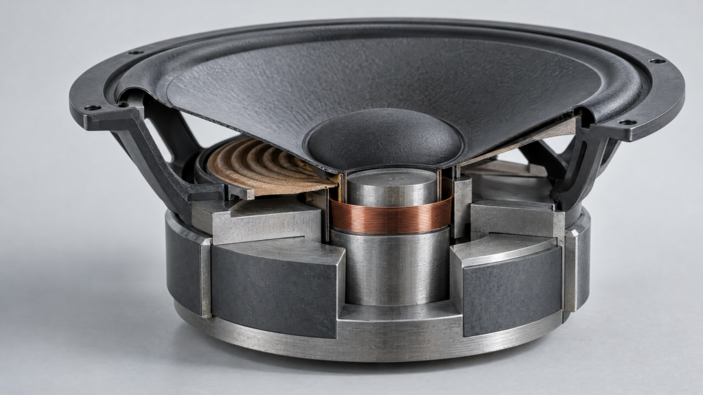
4 Key Benefits of Using a Steel Yoke
A properly engineered soft magnetic yoke transforms how an assembly performs:
- Concentrates Working Flux: By providing a path with much lower magnetic reluctance than air, the yoke channels flux directly into the target air gap or holding surface.
- Reduces Stray Magnetic Fields: Containing the flux loop prevents interference with nearby sensitive electronics or sensors.
- Reduces Magnet Volume and Cost: An efficient return path maximizes flux utilization, allowing engineers to use thinner or smaller rare-earth magnets (such as NdFeB or SmCo) to achieve the same surface gauss or pull force.
- Provides Structural Rigidity: Rare-earth magnets are brittle. A steel yoke absorbs mechanical shock, supports centrifugal loads in rotating machinery, and simplifies mounting.
Common Magnetic Back Iron and Yoke Materials Compared
The right material depends heavily on whether your magnetic field is static (DC) or time-varying/alternating (AC), as well as your space constraints.
| Material Type | Common Grades | Saturation Flux Density (Bs) | Best For | Key Limitations |
| Low-Carbon Steel | AISI 1008, 1010, 1018, 1020 | ~2.0 – 2.1 T | Static holding assemblies, couplings, DC actuators, housings | High eddy-current losses in AC/high-speed fields; requires plating |
| Electrical Steel (Silicon Steel) | M19, M27, M36 (Non-oriented & Grain-oriented) | ~1.8 – 2.0 T | Motor stators/rotors, laminated yokes, variable-speed drives | Lower mechanical strength; requires stamping & lamination stacking |
| Pure Iron (Soft Iron) | DT4, ARMCO Pure Iron | ~2.15 T | Precision magnetic circuits, pole pieces, medical/lab equipment | Higher material cost; soft/difficult to machine; prone to rust |
| Iron-Cobalt Alloys | Hiperco 50, Permendur (49Fe-49Co-2V) | ~2.35 – 2.4 T | Aerospace motors, extreme miniaturization, high-flux density gaps | Very expensive; complex heat treatment required |
1. Low-Carbon Steel (e.g., AISI 1008 / 1010 / 1018)
Low-carbon steel is the industry workhorse for static magnetic assemblies. Grades with carbon content below 0.10% (such as AISI 1008 or 1010) offer higher magnetic permeability and lower coercivity than 1018 or 1045 structural steels. Always review the annealed B-H curve, as cold-working can degrade magnetic performance.
2. Electrical Steel (Silicon Steel)
When magnets rotate or magnetic fields alternate, eddy currents circulate inside solid steel, generating heat and wasting energy. Adding 1% to 3.5% silicon increases electrical resistivity, while stacking thin insulated laminations (typically 0.10 mm to 0.50 mm thick) blocks eddy-current loops.
3. Pure Iron (DT4 / ARMCO)
With minimal carbon and impurities, pure iron delivers exceptionally high magnetic permeability and low coercivity. It is ideal for DC electromagnets and precision sensor pole pieces where rapid, repeatable magnetic response is required.
4. Specialized Soft Magnetic Alloys (Fe-Co, Fe-Ni)
When space is severely restricted and flux density exceeds 2.1 Tesla, iron-cobalt-vanadium alloys prevent saturation where standard steel would fail. Conversely, nickel-iron alloys (Mu-metal, Permalloy) offer ultra-high initial permeability for magnetic shielding and low-field sensors, though they saturate at much lower flux densities (~0.75–1.5 T).
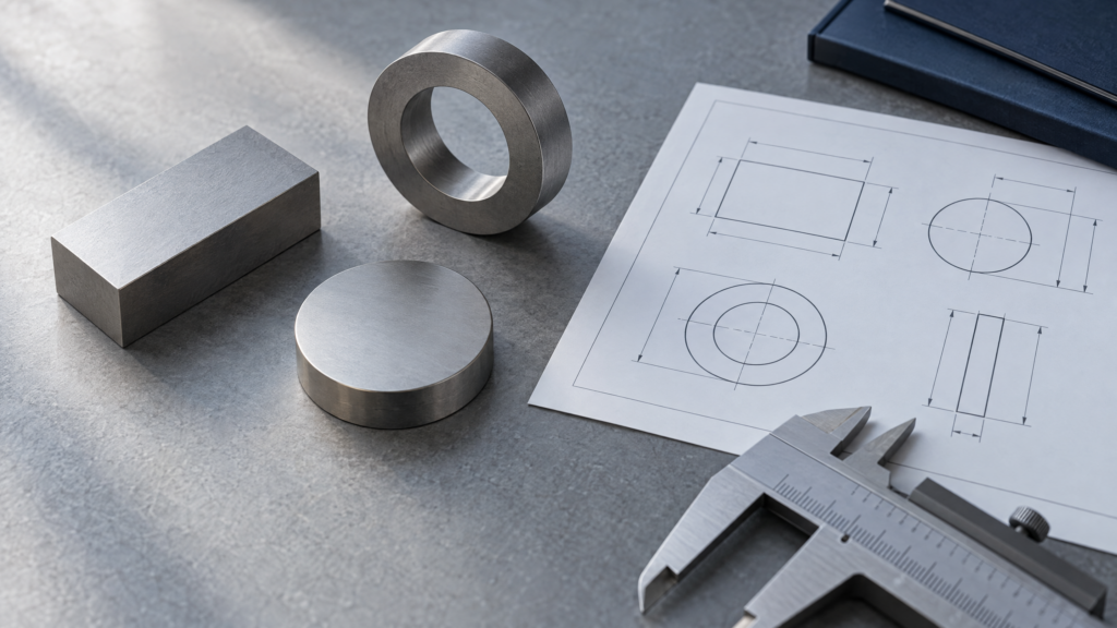
5 Factors for Selecting Back Iron and Yoke Materials
Selecting the right back iron and yoke material requires evaluating both magnetic and mechanical operating conditions.
1. Magnetic Permeability and Operating Point
Permeability (μ) is not a fixed constant—it changes dynamically along the material’s B-H curve. Evaluate permeability at your assembly’s actual operating flux density rather than relying solely on maximum permeability (μmax) datasheet values.
2. Saturation Flux Density (Bs)
Once a yoke reaches magnetic saturation, its relative permeability drops toward 1 (acting like air), causing flux to leak out of the back of the assembly. Design your circuit with a safety margin so the operating flux density in the yoke stays below 75% to 85% of the material’s saturation limit.
3. Core Loss and Operating Frequency
- Static (DC) fields: Solid low-carbon steel or pure iron is sufficient.
- Dynamic (AC) fields: Evaluate hysteresis loss and eddy-current loss based on electrical frequency (f). Higher frequencies require thinner electrical steel laminations or Soft Magnetic Composites (SMCs).
4. Mechanical Stress and Manufacturability
In high-RPM motor rotors, the back iron must withstand intense centrifugal hoop stress without yielding. Consider how the material behaves during CNC machining, laser cutting, stamping, or deep drawing—note that laser cutting and stamping create localized mechanical stress along edges that slightly reduces permeability unless stress-relief annealed.
5. Corrosion Resistance and Coatings
Unprotected low-carbon steel and pure iron oxidize rapidly in humid environments. Common protective finishes include zinc plating, electroless nickel plating, black oxide, or epoxy e-coating. Keep coating thickness tight (typically 5–15 μm) on mating faces to avoid introducing unwanted air gaps.
How Back Iron Thickness and Cross-Section Affect Performance
Even the best soft magnetic alloy will fail if the cross-section is undersized.Magnetic flux density (B) in the return path is governed by:
B = Φ / A
Where:
- B = Flux density in the back iron (Tesla)
- Φ = Total magnetic flux entering the back iron (Webers)
- A = Effective cross-sectional area perpendicular to the flux path ($\text{m}^2$)
Practical Sizing Rule of Thumb
If the back iron is too thin, A decreases, driving B into saturation and choking the magnetic circuit. Conversely, overly thick steel adds unnecessary weight, bulk, and material cost.
Engineering Rule of Thumb: For standard NdFeB magnet assemblies using low-carbon steel back iron, a practical starting point for back iron thickness is roughly 50% to 70% of the magnet’s thickness (assuming a single-sided return path). For high-grade N52 magnets or compact multi-pole arrays, verify exact thickness using 2D/3D Finite Element Analysis (FEA).
Interface Flatness and Air Gaps
The contact interface between the permanent magnet and the back iron is critical. Even a 0.05 mm air gap caused by surface roughness, burrs, or thick adhesive layers adds significant magnetic reluctance. Ensure mating surfaces are ground flat and free of debris prior to bonding.
Back Iron Design in Permanent Magnet Motors
In electric motors, back iron geometry directly dictates torque density and efficiency:
- Stator Back Iron (Yoke): Connects the stator teeth and carries half the flux per pole. Excessive stator yoke saturation increases magnetizing current and iron losses.
- Rotor Yoke: Carries flux between adjacent rotor magnets. In Surface Permanent Magnet (SPM) motors, solid high-strength alloy steel is sometimes used for the rotor hub when eddy currents are low, whereas Interior Permanent Magnet (IPM) motors almost always use laminated electrical steel to house embedded magnets and withstand high speeds.
Common Mistakes in Back Iron and Yoke Design
| Common Mistake | Engineering Consequence | Recommended Approach |
| Using high-carbon or stainless steel (e.g., 304/316) | Austenitic stainless steel is non-magnetic; high-carbon steel has poor permeability | Specify low-carbon steel (1008/1010) or ferritic/martensitic grades (410/430) if corrosion resistance is needed |
| Sizing back iron too thin | Local saturation, flux leakage out the back, reduced pull force/torque | Calculate cross-section via B = Φ / A and validate with FEA simulation |
| Using solid steel in high-frequency AC motors | Severe eddy-current heating, demagnetization risk for magnets | Switch to insulated electrical steel laminations (e.g., 0.20–0.35 mm) |
| Ignoring machining or stamping stress | Degraded permeability near cut edges | Perform hydrogen or vacuum annealing after machining for precision parts |
| Thick adhesive or paint between magnet and yoke | Unintended air gap increases reluctance and drops circuit efficiency | Machine tight tolerances and apply thin, controlled bonding layers |
Need Custom OEM Permanent Magnet Assemblies?
Selecting the right combination of magnet grade, back iron and yoke alloy, and surface coating can significantly reduce your assembly footprint and total BOM cost.
Have a drawing or magnetic requirement in mind? Contact our engineering team today for a free magnetic circuit review and FEA flux simulation. We manufacture custom CNC-machined steel yokes, laminated cores, and fully bonded permanent magnet assemblies built to your exact tolerances.

Frequently Asked Questions (FAQs)
What is the best material for magnetic back iron and yoke?
There is no single best material for every design. AISI 1008/1010 low-carbon steel is the most cost-effective choice for static DC assemblies, laminated silicon steel (M19/M27) is standard for AC motors, pure iron (DT4) excels in precision DC pole pieces, and iron-cobalt alloys (Hiperco 50) are used when maximum saturation density is required in tight spaces.
Can stainless steel be used as magnetic back iron?
Standard 300-series stainless steels (304 and 316) are austenitic and non-magnetic, making them unsuitable as back iron. However, 400-series stainless steels (such as 410, 416, or 430) are magnetic and can be used as back iron when mild corrosion resistance is needed without plating, though their saturation flux density (~1.5–1.7 T) is lower than low-carbon steel.
How thick should magnetic back iron be?
As a baseline rule of thumb for NdFeB magnets on low-carbon steel, back iron thickness is typically 0.5 to 0.7 times the magnet thickness. Exact thickness depends on pole pitch, magnet grade, and material saturation limits, and should be confirmed using magnetic FEA software.
Does thicker back iron always improve magnetic performance?
No. Once the back iron is thick enough to prevent magnetic saturation (typically keeping flux density below 1.6 T in low-carbon steel), adding extra thickness yields negligible gains in working air-gap flux while increasing weight, size, and manufacturing cost.
What is the difference between back iron and a magnet yoke?
Back iron specifically refers to the soft magnetic plate, ring, or housing placed directly behind a magnet to capture and redirect rear flux. A magnet yoke refers to the complete soft magnetic return structure connecting opposite magnetic poles. In most assemblies, the back iron forms the primary section of the yoke.