


A permanent magnet may have a strong magnetic field at its surface, but the field available at a working distance can be significantly different. In many magnetic systems, the distance between the magnet and the target—or between two magnetic components—plays an important role in determining the magnetic field strength.
This distance is commonly referred to as the magnet air gap.
Understanding the air gap is essential when designing permanent magnet circuits, magnetic sensors, encoders, holding systems, and other magnetic assemblies. Even a small increase in the gap can increase magnetic reluctance and reduce the magnetic flux density available in the working region.
In this comprehensive guide, we explain how to analyze a magnet air gap and how it affects magnetic field strength, how to estimate its influence using a simplified magnetic circuit model, and which factors engineers should consider when designing a practical magnetic system.
What Is a Magnet Air Gap?
A magnet air gap is the non-magnetic space between two magnetic components or between a magnet and the component through which its magnetic flux is intended to pass.
The gap may contain air, a non-magnetic spacer, a sensor package, an adhesive layer, or another material with relatively low magnetic permeability.
In a permanent magnet circuit, magnetic flux travels through the magnet and surrounding magnetic materials. When the flux crosses an air gap, it encounters a region with much lower permeability than a typical soft magnetic material.
This increases the reluctance of the magnetic circuit.
The air gap is therefore not simply a mechanical clearance. It is also an important magnetic design parameter.
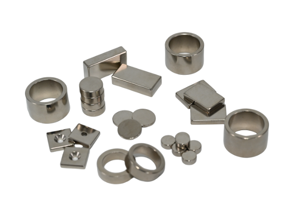
How Does an Air Gap Affect Magnet Strength?
The effect of an air gap is best understood by separating three related quantities:
- Magnetic field strength ($H$): The magnetizing field, measured in amperes per meter ($\text{A/m}$).
- Magnetic flux density ($B$): The magnetic flux per unit area, measured in tesla ($\text{T}$).
- Magnetic flux ($\Phi$): The total magnetic field passing through a given area, measured in webers ($\text{Wb}$).
In an air gap, the relationship between magnetic field strength and flux density is approximately:
$$B_g = \mu_0 H_g$$
where:
- $B_g$ is the magnetic flux density in the air gap;
- $H_g$ is the magnetic field strength in the air gap;
- $\mu_0$ is the permeability of free space.
The air gap introduces additional magnetic reluctance. As the gap becomes longer, the magnetic circuit generally requires more magnetomotive force to maintain the same magnetic flux.
For a permanent magnet operating without additional coil excitation, increasing the air gap often moves the magnet to a different operating point on its demagnetization curve. The result is usually a lower flux density in the working gap.
However, the exact reduction depends on the magnet geometry, the magnetic materials, the pole area, the return path, leakage flux, and the field measurement location.
A larger air gap does not produce one universal percentage of magnetic field loss. The change must be evaluated for the actual magnetic circuit.
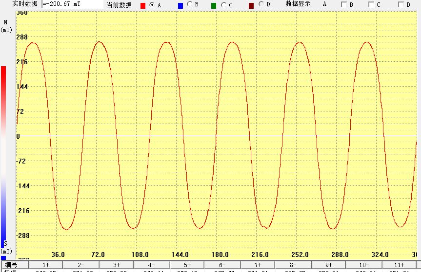
The Relationship Between Air Gap and Magnetic Reluctance
Magnetic reluctance describes how strongly a magnetic circuit opposes the establishment of magnetic flux. It is analogous to electrical resistance in an electrical circuit.
For a uniform air gap, a simplified reluctance equation is:
$$\mathcal{R}_g = \frac{g}{\mu_0 A_g}$$
where:
- $\mathcal{R}_g$ is the air-gap reluctance;
- $g$ is the air-gap length;
- $A_g$ is the effective cross-sectional area of the gap;
- $\mu_0$ is the permeability of free space.
This equation shows that, when the effective area remains constant:
- Increasing the gap length increases reluctance.
- Decreasing the gap length reduces reluctance.
- Increasing the effective gap area reduces reluctance.
For a magnetic circuit containing several components, the total reluctance can be approximated as:
$$\mathcal{R}_{total} = \mathcal{R}_m + \mathcal{R}_g + \mathcal{R}_{core}$$
where the terms represent the reluctance of the magnet, air gap, and magnetic return path.
The magnetic flux can then be estimated using the magnetic-circuit equivalent of Ohm’s law:
$$\Phi \approx \frac{F_m}{\mathcal{R}_{total}}$$
where $F_m$ is the magnetomotive force supplied by the permanent magnet.
This simplified relationship explains why a gap can have a strong influence on the flux in a magnetic circuit.
How to Calculate Magnet Air Gap: A Simplified Estimation
A first-order estimate can be made using a simplified permanent magnet circuit.
Assume:
- The magnet has a uniform cross-sectional area.
- The air gap has approximately the same effective area as the magnet.
- The magnetic return path has relatively high permeability.
- Leakage flux and fringing are neglected.
- The magnet operates on an approximately linear recoil line.
Under these assumptions, the air-gap flux density can be approximated by:
$$B_g \approx \frac{B_r}{1 + \mu_{rec} \frac{g}{l_m}}$$
where:
- $B_g$ is the estimated air-gap flux density;
- $B_r$ is the magnet’s remanence;
- $\mu_{rec}$ is the dimensionless relative recoil permeability (e.g., $\mu_{rec} \approx 1.05$ for NdFeB magnets);
- $g$ is the effective air-gap length;
- $l_m$ is the magnet length along the magnetization direction.
This formula is a simplified estimate, not a universal equation for every magnet geometry. More complex magnetic circuits require the relevant geometry, magnetic material properties, and leakage effects to be included.
Example: Estimating the Effect of a 1 mm Air Gap
Suppose a magnet has the following assumed parameters:
- Remanence: $B_r = 1.2\text{ T}$
- Relative recoil permeability: $\mu_{rec} = 1.05$
- Magnet length: $l_m = 5\text{ mm}$
- Air gap: $g = 1\text{ mm}$
Substituting these values:
$$B_g \approx \frac{1.2}{1 + 1.05 \times \frac{1}{5}}$$
$$B_g \approx 1.00\text{ T}$$
Under this simplified model, the estimated air-gap flux density is approximately $1.00\text{ T}$.
This is a theoretical first-order estimate. It should not be treated as the guaranteed field strength of a real magnet assembly. In a practical design, the actual field may be lower because of leakage flux, fringing, the magnetic return path, magnet dimensions, nearby materials, and the location where the field is measured.
Why Magnet Geometry Matters
The air gap is only one part of the magnetic circuit. Magnet geometry can also influence how much flux reaches the working region.
Important geometric parameters include:
- Magnet length along the magnetization direction.
- Magnet cross-sectional area.
- Pole-face area.
- Air-gap area.
- Distance between magnetic components.
- Shape and dimensions of the return path.
For example, a magnetic assembly with a steel return path may guide more flux through the intended gap than a magnet operating without a suitable return path.
The effective air-gap area may also differ from the physical pole-face area because magnetic flux can spread outward near the gap. This is known as fringing.
For this reason, simple equations are most useful during early design calculations. They cannot replace a complete magnetic-circuit analysis when geometry becomes complex.
Magnet Air Gap Design for Sensors and Encoders
In magnetic sensing systems, the air gap is often the distance between the magnet and the sensing element.
This distance can affect the magnetic field detected by the sensor and therefore influence the output signal.
For Hall effect sensors and magnetic encoders, engineers may need to consider:
- Magnet-to-sensor distance.
- Magnet dimensions and pole configuration.
- Sensor position relative to the magnet.
- Required field strength at the sensing point.
- Mechanical tolerance and assembly variation.
- Operating temperature.
- The sensor’s specified operating range.
The relationship between distance and field strength depends on the magnet’s shape and magnetization pattern. A simple bar magnet, a multipole ring magnet, and a magnetic assembly with a steel return path can produce very different field distributions.
Therefore, the air gap should be evaluated at the actual sensor location rather than inferred only from the magnet’s surface field.
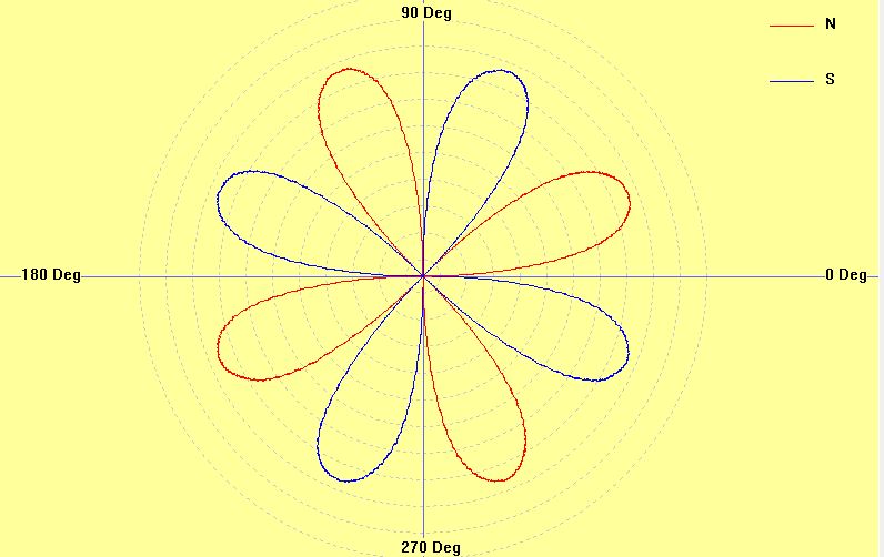
How to Reduce Magnetic Field Loss Across an Air Gap
If the magnetic field in the working region is lower than required, several design options may be considered.
- Reduce the Effective Air Gap Reducing the distance between magnetic components can lower the air-gap reluctance. However, the minimum gap must also account for mechanical clearance, assembly tolerance, vibration, and the movement of any components.
- Optimize the Magnet Dimensions Increasing the magnet length along the magnetization direction may improve the operating point in some magnetic circuits. Changing the magnet cross-sectional area or pole-face geometry may also affect the flux available in the working region. The result depends on the complete magnetic circuit, so the dimensions should not be changed in isolation.
- Improve the Magnetic Return Path A properly designed high-permeability return path can help guide magnetic flux through the intended region. The return path must be evaluated for material properties, geometry, and possible saturation.
- Evaluate Leakage and Fringing Not all magnetic flux travels through the intended working gap. Leakage paths and fringing can affect the effective gap area and the field distribution. These effects become especially important when the gap is large relative to the pole dimensions or when the magnetic geometry is irregular.
- Verify the Field at the Actual Working Location A magnet’s surface field does not automatically represent the field available at the sensor, target, or working gap. Field measurements or magnetic simulation should use the actual working location and the intended assembly configuration.
Air Gap Calculation vs. Magnetic Field Measurement
A calculated air-gap field is useful for preliminary design. It provides an estimate based on assumed dimensions and magnetic properties.
A measured field provides information about a specific physical assembly and measurement location.
For engineering validation, the following should be defined:
- The measurement location and orientation.
- The air-gap dimension.
- The assembled magnetic components.
- The field measurement instrument.
- The temperature and operating conditions.
- The acceptance range.
For complex designs, finite element analysis (FEA) can help evaluate field distribution, leakage flux, fringing, and geometry changes before manufacturing.
The calculation, simulation, and measurement should be treated as complementary methods rather than interchangeable results.
Conclusion
The magnet air gap is an important factor in permanent magnet circuit design because it affects magnetic reluctance and the flux density available in the working region.
A simplified magnetic circuit model can help engineers estimate how changes in gap length may influence the magnetic field. However, the actual result depends on the magnet geometry, magnetic return path, leakage flux, fringing, material properties, and measurement location.
For sensors, encoders, and other precision magnetic assemblies, the most reliable approach is to define the required field at the working location, perform a preliminary calculation, and validate the design through simulation or measurement.
Understanding the relationship between air gap and magnetic field strength helps engineers make better decisions about magnet dimensions, assembly tolerances, and magnetic circuit design.
Frequently Asked Questions
Does a larger air gap make a magnet weaker?
A larger air gap generally increases magnetic reluctance and can reduce the flux density available in the working region. The amount of reduction depends on the magnetic circuit and magnet geometry.
How do you calculate the air gap of a permanent magnet?
For a simplified magnetic circuit, the air-gap flux density can be estimated using the magnet remanence, relative recoil permeability, magnet length, and effective gap length. Complex designs require additional geometry and material data.
What is the difference between magnetic field strength and magnetic flux density?
Magnetic field strength ($H$) describes the magnetizing field and is measured in $\text{A/m}$. Magnetic flux density ($B$) describes magnetic flux per unit area and is measured in tesla ($\text{T}$).
Why is the air gap important in Hall effect sensors?
The air gap determines the distance between the magnet and the sensing element. This distance affects the magnetic field detected by the sensor and may influence its output.
Can the magnetic field across an air gap be measured directly?
Yes. A suitable magnetic field measurement instrument (such as a Gaussmeter/Teslameter) can measure the field at a defined location. The measurement must specify the location, orientation, assembly configuration, and operating conditions.