



Confirming magnet polarity is critical for almost every permanent magnet assembly. In brushless motors, Hall-effect sensors, rotary encoders, magnetic couplings, and automation actuators, a single magnet installed with reversed pole orientation can cause severe torque ripple, signal inversion, or complete system failure.
Verifying pole orientation on a 2D engineering drawing does not guarantee that finished assemblies are error-free. Operator error, flipped parts in automated feeders, fixture wear, or incomplete magnetization can all introduce polarity defects during production.
This quality control (QC) guide explains how to check magnet polarity, verify magnetization after assembly, inspect multipole rings, and build a repeatable production inspection workflow.
Why Magnet Polarity Testing Matters After Assembly
A permanent magnet can pass incoming dimensional and material grade inspections and still fail in the final product. For example, an axially magnetized disc magnet may have exact outer diameter and thickness tolerances yet be bonded upside down inside a sensor housing or rotor pocket.
Dimensional gauges cannot detect magnetic orientation. Post-assembly magnet polarity inspection catches critical defects before components are sealed or shipped:
- Reversed Poles: North and south poles installed opposite to the engineering drawing.
- Angular Orientation Errors: Diametrically magnetized cylinders or shafts misaligned with a keyway, flat, or mechanical datum.
- Multipole Sequence Errors: Incorrect alternating N-S pole patterns or wrong pole count on encoder rings.
- Weak or Unmagnetized Poles: Partial magnetization caused by insufficient capacitor discharge energy or coil misalignment.
- Assembly-Induced Field Distortion: Unexpected flux shifts caused by adjacent steel housings or back iron.
4 Key Parameters to Verify During Magnetization Inspection
Before selecting test equipment, define your acceptance criteria across four distinct magnetic parameters:
- North and South Pole Identification: Confirms whether the intended North or South pole faces the active working surface or air gap.
- Magnetization Direction Relative to Mechanical Datums: Verifies that the magnetic axis aligns with physical reference features (such as a shaft keyway, housing notch, or mounting hole) within angular tolerance (typically ±1° to ±3° for encoders and motors).
- Multipole Pattern and Pole Sequence: Validates total pole count, alternating N-S sequence, pole pitch (spacing), zero-crossing transition angles, and pole-to-pole amplitude consistency.
- Magnetic Field Strength and Distribution: Measures actual flux density (in Gauss or Tesla) at a specified working air gap—because a magnet can have correct polarity while still being under-magnetized.
Comparison of Magnet Polarity Testing Tools
Different production stages require different inspection tools. Use the table below to match the right instrument to your accuracy and throughput requirements:
| Inspection Tool | What It Measures | Best Application | Key Limitations |
| Electronic Pole Indicator (Polarity Pen) | Local N/S polarity (LED or digital sign) | Quick incoming checks, manual assembly line verification | Does not measure flux density or full field distribution |
| Hall-Effect Gaussmeter | Quantitative flux density (Gauss/mT) + polarity | Engineering validation, lab QC, air-gap flux verification | Highly sensitive to probe distance and tilt angle; requires a fixture |
| Magnetic Viewing Film (Viewing Paper) | Qualitative visual pattern of magnetic poles and transitions | Visualizing multipole rings, checking pole count, troubleshooting | Cannot provide numerical Gauss values or angular precision |
| Automated Hall-Probe Scanner | Full 360° angular flux waveform (B vs. angle/position) | Mass-production multipole motor rotors and magnetic encoders | Higher equipment cost; requires rotational or linear motion stage |
1. Electronic Pole Indicators
When placed against a magnet face, a pole indicator instantly lights up (typically red for North, green/blue for South). Keep a known reference magnet at the workstation to verify the pen’s battery and sensor response at the start of every shift.
2. Hall-Effect Gaussmeters
A gaussmeter with an axial or transverse Hall probe measures both field polarity (+ or -) and magnetic flux density. Because flux density drops rapidly with distance, use a non-magnetic (aluminum or Delrin) fixture to hold the probe at a repeatable standoff distance (e.g., 0.5 mm or 1.0 mm from the magnet surface).
3. Magnetic Viewing Film
Magnetic viewing film contains micro-capsules of nickel flakes suspended in oil that align with magnetic field lines. Dark regions indicate pole faces, while bright lines show the neutral transition zones between opposite poles—making it ideal for a 5-second visual check of multipole arrays.
4. Reference Magnets and Go/No-Go Fixtures
For high-volume production, build a dedicated poka-yoke (error-proofing) fixture integrated with a fixed Hall sensor and a certified “Golden Sample” reference assembly.
Step-by-Step: How to Verify Magnet Polarity in an Assembly
Follow this standardized 5-step procedure for post-assembly inspection:
- Review the Approved Engineering Drawing: Confirm the latest drawing revision, required N/S pole locations, mechanical datum surfaces, and whether the datum calls out North-seeking or South-seeking pole convention.
- Lock the Assembly in a Reference Fixture: Seat the housing, shaft, or rotor against a fixed mechanical locating pin or keyway so every part is tested in the exact same orientation.
- Locate Defined Test Points: Position the pole indicator or Hall probe at the exact coordinates specified on the control plan—never eyeball measurement points on curved or small magnets.
- Measure and Compare Against Golden Sample: Check every magnet pocket or pole face in the assembly. Verify that magnet polarity signs match the certified reference assembly.
- Log Traceable Inspection Data: Record pass/fail status, measured Gauss values, fixture ID, operator, and lot number for full production traceability.

How to Test Multipole Magnetization
Multipole ring magnets and rotor assemblies require verifying the entire magnetic waveform rather than a single point:
- Visual Pattern Check: Wrap magnetic viewing film around the circumference to immediately confirm the total number of poles and check for missing or double-width poles.
- Rotary Hall-Probe Scanning: Mount the multipole assembly on a precision rotary encoder stage while a stationary Hall probe records flux density over a full 360° rotation. Plotting Flux Density vs. Angle reveals peak field variation, pole pitch accuracy, and zero-crossing symmetry.
Establishing a Production Magnet Polarity Inspection Plan
Before releasing a magnetic assembly to mass production, align with your engineering and quality teams on three core controls:
- 100% Inspection vs. Lot Sampling: Apply 100% automated inline inspection when a reversed pole cannot be detected downstream and would scrap an expensive motor or sensor module. Use AQL lot sampling only for stable, poka-yoke-controlled processes.
- First-Article Inspection (FAI): Perform full quantitative gaussmeter mapping and angular scanning whenever a magnetizing coil, fixture, or raw magnet batch changes.
- Standardized QC Documentation: Maintain a clear inspection log covering Part Number, Drawing Revision, Lot Number, Required Pole Sequence, Gaussmeter/Probe Calibration ID, Air-Gap Distance, and Pass/Fail Results.
Troubleshooting Common Magnet Polarity and Magnetization Defects
| Common Defect | Likely Root Cause | Corrective Action |
| North and south poles are reversed | Magnet flipped during manual/automated pick-and-place, or magnetizer leads reversed | Add mechanical poka-yoke features; verify magnetizer polarity before shift |
| Diametric pole axis is rotated | Cylindrical magnet rotated inside fixture during magnetizing or adhesive curing | Index magnet using a flat/notch or magnetize after final mechanical assembly |
| Multipole sequence or pitch is wrong | Wrong magnetizing fixture or improper indexing angle | Run a 360° Hall-probe scan and inspect magnetizing coil windings |
| One pole is weak or missing | Insufficient capacitor voltage, coil overheating, or cracked magnet | Check magnetizer voltage logs, inspect for physical cracks, and re-magnetize |
| Gauss readings vary widely part-to-part | Inconsistent probe air gap, probe tilt, or nearby ferromagnetic tools | Use a rigid non-magnetic test fixture and clear steel tools from the bench |
Tip: Before rejecting a batch, verify your test setup—reversing a Hall probe’s orientation or testing near a steel workbench will invert or distort your readings.
Need Custom Permanent Magnet Assemblies with 100% Polarity Verification?
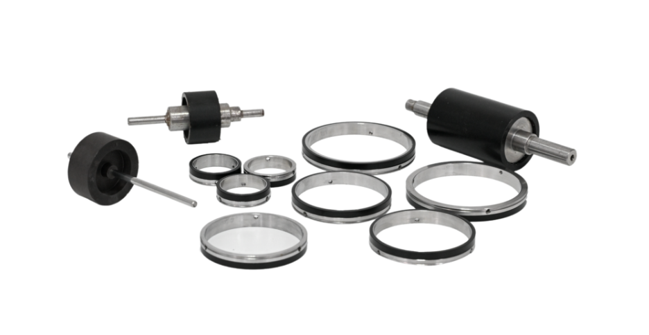
At TNMag, every custom permanent magnet assembly—from high-speed motor rotors and magnetic couplings to precision sensor housings—undergoes strict magnet polarity and flux density verification prior to shipment.
Have a drawing or magnetization specification? Contact our engineering team today to request a custom assembly quote, FEA magnetic simulation, or sample inspection report.
Frequently Asked Questions (FAQs)
How do you check north and south poles of a magnet?
The fastest way to check magnet polarity is with an electronic pole indicator (polarity pen) or a Hall-effect gaussmeter. Always verify your instrument against a certified reference magnet before testing production parts.
Can a gaussmeter identify magnet polarity?
Yes. A Hall-effect gaussmeter displays both the magnetic flux density magnitude and the polarity sign (+ or -), provided you maintain a consistent probe orientation relative to the magnet surface.
How do you verify magnet polarity after assembly?
Secure the finished assembly in a fixture aligned with its mechanical datum (such as a keyway or mounting hole), measure each required pole location using a calibrated Hall probe or pole indicator, and compare the results against the approved drawing and reference sample.
How do you test multipole magnetization?
Combine magnetic viewing film for rapid visual confirmation of the pole count with rotary Hall-probe scanning to measure peak flux density, pole pitch, and zero-crossing angles across all poles.
Does correct magnet polarity mean the magnet is fully magnetized?
No. Checking magnet polarity only confirms that the North and South poles are in the right orientation. You must measure magnetic flux density (in Gauss or Tesla) at a defined air gap to verify that the magnet has reached full saturation.
What should be included in a magnet polarity inspection report?
A complete QC report should include the part number, drawing revision, production lot number, required pole orientation, instrument/probe ID, fixture air-gap distance, measured flux values, pass/fail status, and inspection date.