


A ferrite ring can be dimensionally correct and still be the wrong magnet for a loudspeaker motor. The reason is simple: the driver does not use the magnet by itself. The magnet, pole piece, top plate, back plate or yoke, air gap, and moving voice coil form one electromagnetic system. The design target is therefore not a catalogue value in isolation; it is the field and force behavior the completed motor must deliver over the coil’s working travel.
This guide is for OEM and ODM teams developing moving-coil drivers. It focuses on the information to exchange during design, prototype approval, and sourcing—not on a universal magnet grade or a supplier’s unverified test capability.
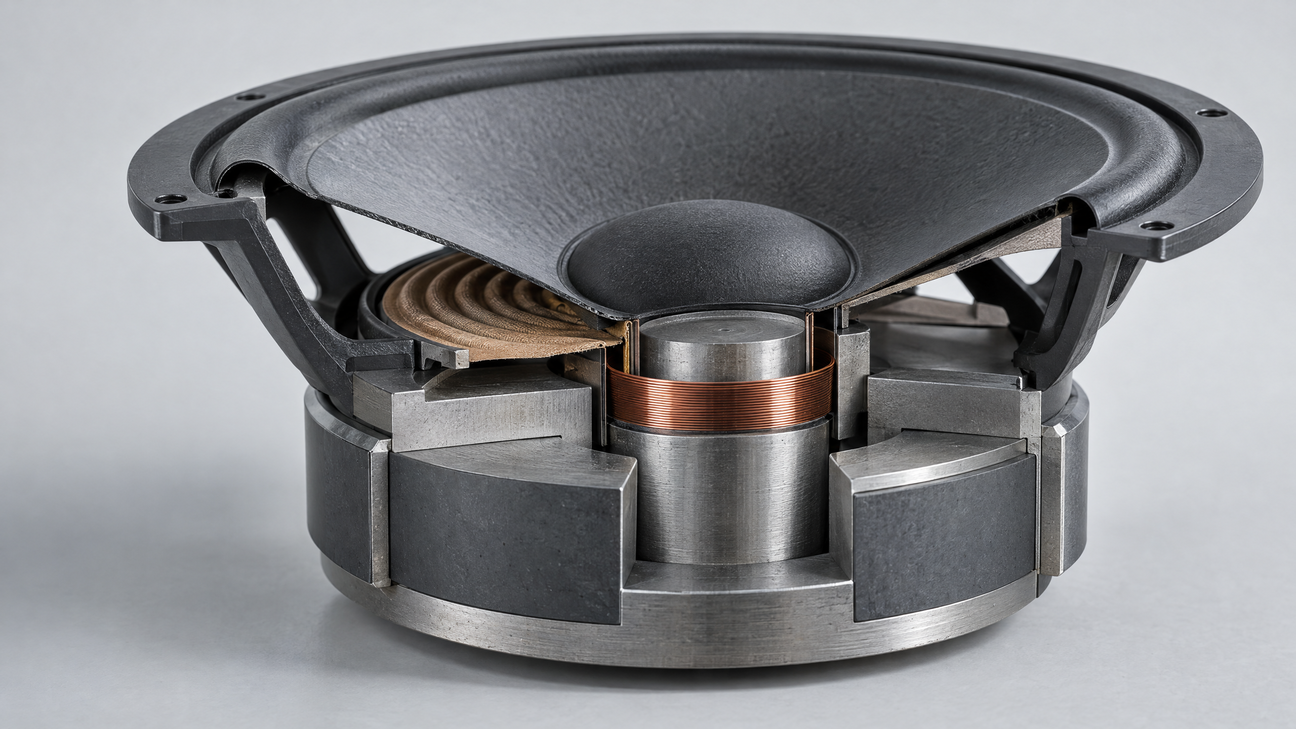
*Concept illustration (AI-generated): a generic loudspeaker magnetic circuit with a ferrite ring, steel plates and pole piece, air gap, and voice coil. This is a conceptual visual only—not a Nibboh product image, a validated engineering drawing, a magnetic-field simulation, or a test result.
Start with the motor, not the ring
In a moving-coil driver, current in the voice-coil conductor interacts with radial magnetic flux in the gap to create force. The force factor, commonly written as Bl, depends on the magnetic field encountered by the winding and on the winding geometry. As the coil moves, its position relative to the field changes; consequently, a single field reading at the rest position cannot describe the full motor behavior. Klippel’s field-scanning paper explains how field density across height and angle, combined with coil geometry, relates to Bl(x), and how field nonuniformity can matter to driver behavior [2].
For an OEM specification, translate the acoustic and mechanical requirements into a motor-level target before freezing the magnet drawing. The design team should agree which quantities matter: for example, the required force-factor curve over the intended excursion, its symmetry around the rest position, the usable linear travel, and any driver-level acoustic limits. Those are project requirements; they are not values that can be inferred from the word “ferrite” or from ring dimensions alone.
A useful engineering sequence is to evaluate the motor as a stack: voice-coil diameter and height; radial and axial air-gap geometry; pole-piece and plate dimensions; steel properties and saturation margin; magnet dimensions and magnetization direction; and assembly tolerances. Small changes in gap width, plate geometry, or coil position can change the useful field distribution. The Politecnico di Milano thesis on loudspeaker magnetic-circuit optimization used Bl(x), curve symmetry, and material use as design indicators, but also notes that a pre-design model did not include every construction variable and required subsequent prototype validation [3]. That is a good reason to treat simulation as a way to narrow design choices—not as final release evidence.
Define the interfaces before choosing a material grade
A supplier cannot reliably quote a speaker-motor ring from “same as sample” or outside diameter alone. The drawing package should state the complete magnetic and mechanical interfaces:
| Definition item | What the project team should specify |
|---|---|
| Magnet geometry | Outside diameter, inside diameter, thickness, relevant chamfers or reliefs, datum scheme, and tolerances tied to the assembly stack-up. |
| Magnetization | Axial or other required direction, which face is north/south, polarity mark or inspection method, and any assembly orientation constraint. |
| Magnetic circuit | Pole piece, top plate, back plate/yoke geometry, material grades or required magnetic properties, air-gap width/depth, and the coil’s operating position. |
| Operating envelope | Coil dimensions, rest position, excursion range, current domain and any temperature exposure that affects the design or test. |
| Acceptance targets | Which measurements are required on the magnet, magnetic circuit, or complete driver; test fixture, sample size, limits, and report format. |
Use a controlled drawing revision and a section view of the assembled motor. Where the steel parts are supplied by another vendor or made by the OEM, identify who owns the magnetic-circuit stack-up and who approves changes. If a project is only sourcing the ferrite ring, say so explicitly; do not let “speaker magnet” quietly become an undefined request for a complete motor assembly.
Select the ferrite by the operating point, not one headline number
Hard ferrite is a permanent-magnet material; it should not be confused with soft ferrite used in transformer or inductor cores. A hard-ferrite ring is one option for a loudspeaker motor, but its suitability depends on the selected material’s demagnetization behavior, temperature conditions, geometry, and the magnetic circuit around it.
When comparing candidate grades, request the complete agreed material data and the test conditions. Remanence and coercivity describe different parts of the material behavior; maximum energy product is not a direct substitute for a motor-level field or force-factor target. IEC 60404-5 defines methods for measuring flux density, polarization and field strength, and for determining the demagnetization curve and recoil line of magnetically hard permanent-magnet materials [5]. It is a material-characterization reference, not a pass/fail standard for an assembled loudspeaker motor.
The public Nibboh hard-ferrite page lists ring, E-shaped and rod forms, names speakers among application areas, and describes a general production sequence [1]. That is useful as a product-category and inquiry starting point. The page does not publish a speaker-specific grade, ring drawing, tolerance, motor assembly, target B or Bl curve, or test report. Those details need to be established for the actual project; the website’s general statements are not evidence that a particular design has been built or validated.
Make the magnetic-circuit model answer a testable question
A practical first model should include the ferrite’s measured material curve, the soft-magnetic parts, the air gap, and the relevant coil geometry. For an axisymmetric ring motor, a 2D model may be an efficient initial step. Add a 3D check when the design has vents, tabs, interrupted plates, non-circular features, or other details that could create angular variation. Choose outputs that can later be measured on a prototype: gap field by height and angle, field uniformity over the winding region, and calculated Bl(x) over the specified travel.
The model should record its assumptions: material curve source and temperature; steel B-H data; contact or bonding assumptions; geometric tolerances; and whether the coil is represented as a field probe, an explicit winding, or an equivalent model. A model that uses ideal geometry and nominal material data can be useful for comparing concepts, but it cannot establish production variation or prove a supplier’s actual inspection capability.
Klippel’s field-scanning work describes direct Hall-sensor measurements of the radial field across height and angle in a driver gap, followed by integrating the field with coil geometry to estimate static Bl(x) [2]. The paper also notes that access to the gap may require removing the coil and diaphragm, and that accurate probe positioning matters where the field changes near the gap edges. For that reason, define early whether the acceptance method is destructive/engineering-sample scanning, a non-destructive fixture, or a driver-level force-factor measurement. These methods answer related but not identical questions.
Separate material checks from motor and driver checks
A useful validation plan has three levels:
1. Magnet lot. Verify drawing dimensions, mass if relevant, visible chips or cracks, orientation/polarity, and the agreed magnetic-material properties on representative samples. If the project relies on a demagnetization curve or recoil line, specify whether the report is for the grade, a representative specimen, or the delivered lot, and identify the test method and conditions. IEC 60404-5 is relevant to material-property measurement, but the buyer and supplier still need to agree what data will actually be supplied [5].
2. Assembled motor. On first-article samples, measure the field in the gap at defined heights and circumferential positions, or use another agreed method that represents the assembled geometry. Compare the measured map with the model and establish what level of angular variation or position-dependent change is acceptable. If Bl(x) is a key target, specify whether it is calculated from field and coil geometry or measured on a prototype, and how the coil position and current are controlled. Dodd, Klippel and Oclee-Brown also discuss how loudspeaker motor geometry and material influence voice-coil impedance, including its variation with displacement [4]; a field map should therefore be considered one part of a broader driver evaluation.
3. Complete driver. Evaluate the finished transducer under the project’s acoustic and electrical requirements. IEC 60268-21:2018 covers physical, output-based acoustic measurements on electro-acoustic transducers and sound systems [6]. It does not certify a magnet supplier, prescribe the magnet’s grade, or replace a motor-specific magnetic-field acceptance plan. The older IEC 60268-5:2003 page is listed as withdrawn by IEC, so it should not be cited as the current standard without checking the applicable replacement and market requirements [7].
Build purchasing evidence into the RFQ and sample approval
For sourcing, ask for evidence tied to the exact drawing revision and production configuration—not a generic capability statement. A focused RFQ can request: the magnet drawing and material designation; magnetization direction and polarity convention; agreed dimensional and magnetic characteristics; a first-article inspection report; sample lot identification; any measured motor field or Bl(x) data the project requires; a description of the measurement fixture and conditions; packaging and handling controls for brittle ceramic parts; and a written change-notification process for material, geometry, tooling, magnetization or production-route changes.
If the supplier is quoting only a ferrite ring, the OEM should retain responsibility for the pole pieces, gap, stack-up, coil geometry and completed-driver acceptance unless the contract explicitly assigns those tasks elsewhere. If the supplier is asked to provide a magnetic assembly or engineering support, the RFQ should define the deliverables and demonstrate them through a project-specific sample and test plan. Do not assume that a product webpage, a generic process flow, or a catalogue value proves that the supplier has a particular Hall scanner, finite-element workflow, acoustic laboratory, certification or production capacity.
A practical first RFQ package
Send a controlled assembly drawing with a section through the voice-coil gap, the ring-magnet drawing, pole/plate interface drawings, magnetization/polarity requirements, material and operating conditions, and the project’s Bl(x) or gap-field targets. Add the intended test levels—material coupon, motor assembly, and complete driver—and identify who owns each test and who signs off deviations. That gives the magnet supplier enough context to discuss feasibility while keeping system-level performance claims attached to the evidence that can actually verify them.
References
- Nibboh — Hard Ferrite Magnet. Public product-category page; not a project-specific performance record.
- Wolfgang Klippel, “Scanning the Magnetic Field of Electro-dynamic Transducers”. Hall-probe field mapping and relation of gap field to Bl(x).
- Bruno Sciarrone, Topologic Optimization of Magnetic Circuits in Loudspeakers, Politecnico di Milano, academic year 2022–23. A specific FEM optimization case; not an industry-wide performance benchmark.
- Mark Dodd, Wolfgang Klippel and Jack Oclee-Brown, “Voice Coil Impedance as a Function of Frequency and Displacement”.
- IEC 60404-5:2015, Magnetic materials — Permanent magnet (magnetically hard) materials — Methods of measurement of magnetic properties.
- IEC 60268-21:2018, Sound system equipment — Part 21: Acoustical (output-based) measurements.
- IEC 60268-5:2003 lifecycle page, which IEC lists as withdrawn on 17 April 2026.